Add a Pipe or Duct Line
Add a pipe or duct line by indicating the route of its center
line with points.
- Do either of the following:
- Select
 Pipings > Add Pipe
Line.
Pipings > Add Pipe
Line.
- Select Pipings >
 Add Duct
Line.
Add Duct
Line.
- Select properties in the fields of the contextual toolbar.
 Pipe or Duct Line
Properties
Pipe or Duct Line
Properties
- Indicate the starting point for the center line. The program
will ask you for the point's height position in the dialog box.
Enter Height
Position in the Dialog Box
You can also use a component grip point as the starting
point.
Begin Routing from a
Component
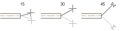
- Determine the sweep direction.
- If you selected a component grip point as the starting point,
the default direction is the one determined by the grip point. The
cursor is locked in this direction.
- If you selected some other point, you can lock the cursor as a
ruler.
- You can lock the Z axis direction as the desired direction by
pressing the O key.
- Do either of the following:
- Determine the sweep direction. The sweep direction is affected
by the bend radius of an elbow added between straight parts. If
necessary, select the elbow again.
- Continue adding the line by clicking the next point.
- You can return to the previous point by pressing Ctrl+Z and
click the next point again.
- You can undo the added points of the same line all the way back
to the starting point.
- Select Confirm.
- Quit by pressing the Esc key.
 Note
Note
- Pipe and duct lines of varying types are added on their own
layers. For example, sewer pipes are added on layer 193. BY
default, the layers shown in the floor plan vary on a
customer-specific basis.
- Pressing the K key shows the directions of the coordinate axes
at the cursor.
- You can change the size of the pipe/duct by first adding a
narrowing volume of the desired size from the component
library.
- When you select the center line of another line as the point of
a pipe or duct line, a browser for selecting branch components is
opened.
- If you do not define the position or length of a pipe or duct
component accurately when it is modeled, it will be positioned in
the assembly using geometric constraints.
- You can also model a pipe or duct line by adding parts from the
component library.
Change
Pipe/Duct Size
Add a Pipe or Duct
Component
Edit Slope
Position the Parts
of a Pipe or Duct Line Using Constraints
 Route Pipe or Duct Line
Setting Layers as
Visible
Locking the
Cursor