Defines the data of a text or a dimension selected for editing, such as text content, dimension tolerance and dimension precision, and other data of the element. Define the text and dimension properties in the dialog box.
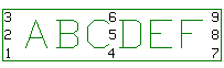
Part numbers and engineering drawing symbols are also texts.
![]() Editing Text
Properties
Editing Text
Properties
![]() Editing Dimension Properties
Editing Dimension Properties
Editing Text
Enter the text content in the Text field. You can enter more than one line, if you select the Enter as line break checkbox. Create a line break by pressing the Enter key.
Open the special character menu by clicking the Character button.
You can select the insertion point of the text by clicking a radio button. You can align the text to the left, center, or right. Select the insertion point by clicking the Insertion point radio button. If you want the insertion point to be in the middle of the text field, mark the Center alignment point checkbox. There are nine options for the insertion point.
Editing Dimension
When defining a dimension tolerance or editing a dimension, the dimension figure will be depicted in the Text field. You can edit the dimension by adding characters to it or replacing it with text. You can copy and paste characters in the Text field. If the dimension value disappears from the field, you can restore the original dimension value in the field by clicking the Dimension value button.
Mark
Defines a special character to be inserted in the Text field. Click the button and select a special character. It will be added to the string at the cursor position when the function is selected.
Dimension value
Restores the dimension value into the empty Text field.
Formula
Defines the variable of the dimension figure.
Text number increment
Sets the automatic text number increment in use, when this checkbox is selected and the increment specified.
When the inserted text is numerical and your intention is to add sequential numbers to a drawing, the program will automatically add the specified increment to the inserted number.
Arrows
Automatically (default) defines the dimension arrows based on where you click the position of the dimension on the dimension line. Change the dimension arrows to Inside or Outside by clicking the selection button.
Drives geometry
Defines a dimension to act as a geometric constraint, when this checkbox is selected. You can edit the geometry by editing the numerical value of the dimension constraint in the Text field. The dimension added to the intersection point of lines will not be updated and cannot act as a constraint, when the geometry is changed.
Fake dimension
The dimension value is set as a constant, when this checkbox is selected. You can specify a value for a dimension that differs from the actual value. You cannot use this feature for dimensions that act as constraints. When the geometry is changed, the extension lines will be updated only, not the dimension figure.
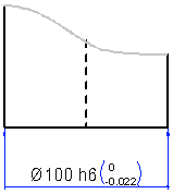
Tolerance
Defines a dimension tolerance to be added to a dimension. You can a tolerance in the field in the following ways.
Tolerance symbol
If you enter the tolerance symbol in the Tolerance field. The program will also add deviations to the dimension.
For example, h6.
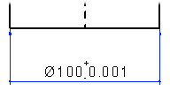
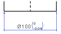
Deviations
You can enter deviations in the Tolerance field in the following ways.
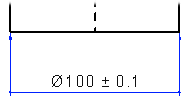
+-0.001
0 -0.04
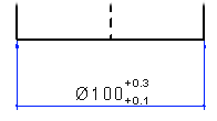
+0.3 +0.1
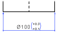
+0.3,+0.1
Adding the tolerance in the Text editing window
You can add deviations to the dimension as follows:
Move the cursor after the dimension number in the Text editing window.
Add the whitespace character.
Click the Character button and select the
![]() character from the list.
character from the list.
Add the whitespace character after special character.
Enter the deviation. For example, 0.1.
Precision
Defines the dimension precision that is the number of decimals in the dimension.
You can select a single or several dimension
figures in a drawing, and edit the precision of the seleceted
dimensions. ![]() Editing the
Dimensioning Precision of Dimensions
Editing the
Dimensioning Precision of Dimensions
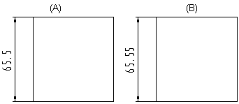
The default dimension precision value is 0.1. You can select the precision from the list or enter the precision value. The program will also accept values that are higher than 1, for example 10.
Changing the dimension precision from 0.1 (A) to 0.01 (B) is shown in the number of decimals in the dimension.
Inch conversion
Defines the precision of the inch conversion of a dimension. Inch conversion is dimension-specific. Select the appropriate precision in the Inch conversion list.
![]() At this point, the dimension is not yet
changed to the inch dimension.
At this point, the dimension is not yet
changed to the inch dimension.
Inch conversion can be simultaneously performed
on all dimensions of a drawing using the Dimensions>
![]() Convert dimensions to inches. The conversion will take
dimension-specific precisions into account.
Convert dimensions to inches. The conversion will take
dimension-specific precisions into account.
![]() Converting Dimension to
Inches
Converting Dimension to
Inches
![]() Text and Dimension
Properties
Text and Dimension
Properties
![]() Dimension End Markers
Dimension End Markers
![]() Dimension Tolerancei
Dimension Tolerancei
| Converted from CHM to HTML with chm2web Pro 2.85 (unicode) |