You can select the framed exterior wall's parameters used in the wall panel design by clicking the Framing button in the Wall Selection dialog box. Parameters are customer-specific. Some basic parameters are described in this guide.
On this tab, you can define the parameters required in wall panel design (included in the Vertex BD Framer product). The default values for the parameters are read from the project parameters.
Framing Detail
Select from the list.
Panel Label
The first part of the wall panel label.
Ext, Corner Type, Int. Corner Type, Backer
Details of a rectangular corner and backers. Click the Sel button, and select a detail from a drawing window by clicking the hot spot. The detail of an angled corner is defined in the project parameters.
Stud Spacing
The distance between the studs of a wall panel measured from center to center. Select from the list.
Stud Start From
The starting point of the studding of a wall panel. Select the radio button Right, Left, Center or Left/Right. The right and left of the wall are determined by the viewing direction.
Center Stud
The center stud of a wall panel can be either a single or a double stud. Select the radio button Single or Double.
On this tab, you can define the parameters required in wall panel design (included in the Vertex BD Framer product). The default values for the parameters are read from the project parameters.
Top Type
Click the Sel button, and select a detail from a drawing window by clicking the hot spot. If necessary, select a dimension connected to the detail from the Dimension list, or type a value in the text field.

Top Plate
Select the cross section from the profile library by clicking the Sel button.
If you select an option with a beam, also select the Beam Along Top Pl. cross section from the profile library by clicking the Sel button.
Head binder
Select the cross section from the profile library by clicking the Sel button.
Bot. Type
Click the Sel button, and select a detail from a drawing window by clicking the hot spot. If necessary, select a dimension connected to the detail from the Dimension list, or type a value in the text field.

Bottom plate
Select the cross section from the profile library by clicking the Sel button.
If you select an option with a beam, also select the Beam Along Bottom Pl. cross section from the profile library by clicking the Sel button.
Stud
Select the cross section from the profile library by clicking the Sel button.
Select single or double studs by selecting an option from the No list.
Block
Select blocking by selecting the check box Horiz. (A) or End (B), or both.

Select the cross section of the blocking by clicking the Sel button. Select the position height of the blocking from the Height list, or type the height in relation to the floor base height in the text field.
Select the Type of the blocking from the list:

On this tab you can select the window and door details to be used in the wall panel design.
Header #1, #2, #3
The use of the details is determined as follows:
Detail Header #1 is used when the width of the opening is smaller than or equal to the value in the Max field on the same row.
When the width of the opening exceeds the maximum width of Header #1, detail Header #2 is used.
When the width of the opening exceeds the maximum width of Header #2, detail Header #3 is used.
Click the Sel button, and select a detail from a drawing window by clicking the hot spot.
Select the cross section of the beam to be used in the opening details from the profile library by clicking the Sel button.
Select the maximum width of the opening from the Max list.
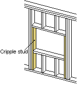
Cripple Stud
Select the cross section of the cripple stud from the profile library by clicking the Sel button. Select the number of the cripple studs from the list.

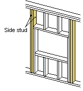
Side Stud
Select the cross section of the side stud from the profile library by clicking the Sel button. Select the number of the side studs from the list.

On this tab, you can select the parameters of the sheathing to be used in the wall panel design. Select the sheets from the sheathing library by clicking the Sel button. Move the cursor on the desired row in the Sheathing Properties database view, and click the OK button. The parameters on the Sheathing tab are also updated.
Interior Finish
The interior sheathing of the wall.
Sec. Int. Sheathing
The interior sheathing of the frame.
Structural Sheath.
The exterior sheathing of the frame.
Sheathing
The sheathing on the exterior side of the wall.
Overlap, top
If necessary, define the part (a) of the sheet or vertical nailer overlapping the top edge of the wall panel. Enter the desired value in the text field.

Overlap, bottom
If necessary, define the part (b) of the sheet or vertical nailer overlapping the bottom edge of the wall panel. Enter the desired value in the text field.

Installation space
If necessary, define the installation space (d) of the sheathing. Enter the desired value in the text field.

Siding nailers
If necessary, select the horizontal (A) or vertical (B) siding nailer, or both, in use.

Select one of the following from the list:
Horizontal
0 - Not in use
1 - Used on exterior
2 - Used on interior
Vertical
0 - Not in use
1 - Used on exterior
2 - Used on interior
3 - Used as double
Select the cross section of the nailer by clicking the Sel button. Select the position height of the nailer from the Height list, or type the height in relation to the floor base height in the text field.
![]() Library Data of a Wall with
a Layer Structure
Library Data of a Wall with
a Layer Structure
![]() Editing
Keywords
Editing
Keywords
| Converted from CHM to HTML with chm2web Pro 2.85 (unicode) |