Create a 2D Drawing of a Component from a Part Model
You can create a building component's 2D drawing from a part
model as follows:
- Open the part model in one of the following ways:
- Select File > Open > Open File.
- Open the model from the Windows Explorer using the drag and
drop method.
- You can also open an archived model by selecting the File
> Open > Model function.
- Select the
 Part tab in the left side browser.

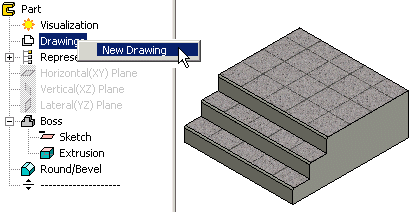
- In the part model's feature tree, right-click Drawings,
and select New Drawing.

- Select the projection data and the scale in the dialog box:
- Select 1:1 as the scale.
- Select projection b: top. Clear the a: front
check box, which is selected by default.
- Clear the Centerlines checkbox.
- Confirm by clicking OK.
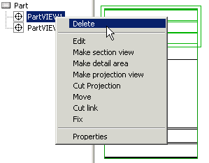
- Remove the extra projection: move the cursor over the
projection label in the projection tree and select the
context-sensitive function Delete.

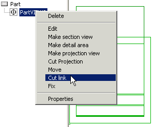
- In order to be able to edit the lines in the drawing, cut the
connection between the projection and the model: move the cursor
over the projection label in the projection tree and select the
context-sensitive function Cut link.

You will be prompted: "Action will destroy
connection to model. Do you wish to proceed?"
- Select Yes.
- Edit the lines in the drawing.
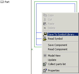
- Open the context-sensitive menu in the drawing and select
Save to Symbol Library.

- Select a component library folder as the saving location, for
example ../custom/complibs/macro_custom, and enter a name for the
drawing.
- Select Normal Symbol (default) in the Parameters of
Symbol dialog box.
- Close the drawing window. You will be prompted: "Save
changes?"
- Select Only Selected.
 Note
Note
- Save the 2D drawing of a window in the
../custom/complibs/win_custom folder, and the 2D drawing of a door
in the ../custom/complibs/door_custom folder.
 Drawing Layer of
Macro Component Lines
 Set Component 2D Drawing in a
Library
 Create a 2D Drawing of a
Component
 Save a Modeled Component in a
Library


