Vertical Walls Extended
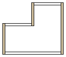
Horizontal Walls Extended
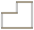
Clockwise
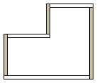
Counterclockwise
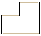
|
Framer |
Select the structural layers, corner overlap type, label, viewing direction of the panel, panel break settings and other settings to be included in the wall panel in the dialog box. The panel break settings are relevant when the maximum length and default length of wall panels are defined to allow one wall to include several panels.
Structural Layers
Select the structural layers to be included in the wall panels. Only the geometry and parts of the selected structural layers are generated in the framing model. The geometry of the structural layers is generated in the framing model when you create the panel breaks. Parts will be created later using a different function.
A wall and a wall panel must always include one frame layer. There can be one or several nailer and sheathing layers on the inside and outside of the frame layer.
Interior Sheathing - Select this to include all the sheathing layers inside the frame layer in the wall panel.
Interior Battens - Select this to include all the nailer layers inside the frame layer in the wall panel. The structural layers between the frame layer and the nailer layer are also included in the panel.
Frame - The frame layer is always included in the wall panel.
Exterior Battens - Select to include all the nailer layers outside the frame layer in the wall panel. The structural layers between the frame layer and the nailer layer are also included in the panel.
Exterior Sheathing - Select to include all the sheathing layers outside the frame layer in the wall panel.
Membranes, Foils - Select all the membrane and foil layers to be included in the wall panel.
Furring Strips - Select the layer behind siding layer that is to be included in the wall panel. The layer can be either an air gap or layer for which no other horizontal batten or sub frame tool has been defined. The furrings can be either vertical or horizontal. If necessary you can define furrings in the opposite direction by checking the option Double Furring. The extra layer is a layer behind the cladding battens. Select the furring strip settings in the Cladding Batten Settings tab in the dialog box.
Siding - Select all the siding layers to be included in the wall panel.
Corner Details
Select how the wall panels are cut in corners. Select one of the following:
Vertical Walls Extended

Horizontal Walls Extended

Clockwise

Counterclockwise

Horizontal walls are the walls parallel to the x-axis in the floor plan drawing, and vertical walls are the walls parallel to the y-axis.
The default corner detail is defined in the WALLS keyword group with the keyword corner_overlap_mode.
Set Panel Label Using
The wall panel label consists of a prefix and a sequential number. The prefix can be read from the wall frame parameters or the user can define the prefix in a dialog box. Select either of the following:
Wall Attributes - The label defined in the wall frame parameters is used as the wall panel prefix. The panels are numbered sequentially, starting from the first unoccupied number in the active drawing-model pair.
Wall Type - Type the first part of the label and the number of the first wall panel in the Exterior Panel and Interior Panel text fields. The default number in the fields is the first unoccupied number in the active drawing-model pair.
Interior View
The default viewing direction of a front projection created in a wall panel drawing is from outside of the wall. The panel labels are added to the outside of the wall in a floor plan drawing. If you wish the viewing direction to be from inside the wall, select the Interior View checkbox. The panel labels are added to the inside of the wall in a floor plan drawing.
The Interior View checkbox is unselected by default if the WALLS keyword group includes the keyword inside_view = 0. If you wish the checkbox to be selected by default, set the keyword value to inside_view = 2.
Wall 1st Panel Length by
The setting is relevant when the maximum length and default length of wall panels are defined to allow one wall to include several panels. The default lengths are defined in the project parameters.
Select how the break point of the first panel of each wall is determined:
Exterior Sheathing - The length of a wall panel (L) is calculated from the end of the exterior sheathing layer closest to the frame layer.
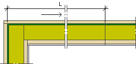
Structural Frame - The length of a wall panel (L) is calculated from the end of the frame layer.
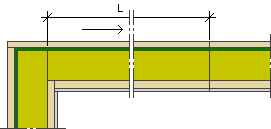
Interior Sheathing - The length of a wall panel (L) is calculated from the end of the exterior sheathing layer closest to the frame layer.
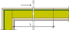
In the example figures, a corner detail included in the basic software delivery is used. The selected direction of the panel breaks is Clockwise.
Drawing-Model Pair
Select the drawing-model pair to which you wish to create the wall panel geometry. The default is Framing.
Active - The opened drawing-model pair.
Framing - Drawing-model pair for structural design. If, for example, the "first floor walls" drawing-model pair is open, the wall panels are created in the "first floor wall, framing" drawing-model pair.
Wall 1st Panel Extra Length
The final length of the first wall panel is the default length + the length offset. You can define the length offset for held back and extended corners separately. Enter the desired value in the field. The value can be negative, in which case the length offset is deducted from the default length of the panel.
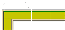
At Held Back Corner: L = default length + length offset for a held back corner.
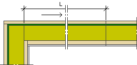
At Extended Corner: L = default length + length offset for an extended corner.
Panelization Direction
Select the direction in which to rotate the walls and add the panel break points. The panels are numbered in sequence according to the selected direction, if you select to panel all of the walls at the same time.
Counterclockwise
Clockwise
If you would like to add frame studs in the same direction, select the option Set Stud Rule According to Panelization. If the checkbox is empty, the stud rule defined in the framing tool of the frame is used (the studs begin from the right, left or middle).
Set Layer Thicknesses by Framing Rule Definitions
In conjunction with the creation of the wall panel breaks, the program checks the compatibility of the wall layers and the framing tools selected for them. If necessary, the program changes the layer thickness to suit the selected tool. If the setting is disabled, the program will only issue a warning but will not change the layer thickness.
Merge Compatible Furrings
This setting is significant if you have selected the layers Furring Strips and Double Furring (in the Basic tab) for the panel. If the siding is divided into sections (for example, vertical-horizontal-vertical), the program will also divide the furring layer and extra layer into matching sections. If the setting is enabled, the program will merge the extra layer pieces automatically, if they are compatible. The pieces are compatible when the same framing tools have been selected for them.
Alternatively, you can merge the extra layer parts in the model by processing the wall parts.
![]() Merging a Wall
Volume with a Wall Layer
Merging a Wall
Volume with a Wall Layer
Add Battens Behind Wall Trims
If the siding has been divided into sections by a trim, the setting will stretch the batten layer to reach under the siding trim as well. The program tries to stretch the layer according to the vertical siding. If the siding trim is located between vertical sidings, the batten layer of the lower siding will be stretched under the siding trim.
Shrink Battens by Air Gaps
When the setting is enabled, the air gap restricts the shape of the batten layer. The shape of the layer is determined by the intersection of the batten area formed based on the sidings and the air gap. This requires that the batten area and the air gap overlap each other at least 60 %.
Furring Strips
The settings can be selected when the Furring Strips layer is selected to be included in the wall panel. The layer can be either an air gap or layer for which no other horizontal batten or sub frame tool has been defined. If the siding is divided into sections (for example, vertical-horizontal-vertical), the program will also divide the batten layer into matching sections. Select one of the following as the direction for the battens:
Horizontal - Select the framing tool with the Frm. Settings, horiz button.
Vertical - Select the framing tool with the Frm. Settings, vert button.
Dir from Siding - The direction of the battens is defined according to the siding: vertical battens for horizontal siding, and horizontal battens for vertical siding. Select the framing tools for both directions with the Frm. Settings, horiz and Frm. Settings, vert buttons.
Select the tool in the Framing Tools dialog box. You can edit the tool parameters after creating the panel breaks.
Double Furring
The settings can be selected when the layer Double cladding battens is selected to be included in the wall panel. The extra layer is a layer behind the cladding battens. Select the direction and settings as you would for the cladding battens.
If the siding is divided into sections (for example, vertical-horizontal-vertical), the program will also divide the furring layer and extra layer into matching sections. If necessary, you can merge the extra layer parts in the model by processing the wall parts.
![]() Merging a Wall
Volume with a Wall Layer
Merging a Wall
Volume with a Wall Layer
Alternatively, you can check the Merge Compatible Furrings option in the Advanced tab to merge the parts of the double furring layer automatically if they are compatible. The pieces are compatible when the same framing tools have been selected for them.
![]() Generate
Wall Panel Breaks
Generate
Wall Panel Breaks
![]() Editing
Keywords
Editing
Keywords
| Converted from CHM to HTML with chm2web Pro 2.85 (unicode) |