Draft Accuracy of Geometry
This function can be used to refine the faceting of a part,
where the rectangular and triangular faces formed by the facet
lines are used to make the contours as close to the actual object
as possible.
The program will first facet the volume with a value that it
assumes appropriate. This can be refined if needed. The starting
point for faceting when creating a face is the default value of the
face's portions, based on which the program will create the default
faceting.
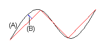
You can achieve the exact shape of the face (A) by reducing the
tolerance value (B) and the angle tolerance value. The angle
tolerance affects the mesh formed by triangular faces on rounded
surfaces. If you decrease the angle tolerance value, the number of
triangles increases and the shape of the surface becomes more
detailed.
When cutting up a volume, the program will again facet the
volume with a calculated value that it assumes appropriate (default
faceting), even if you have refined the faceting.
 A small tolerance value will make the model slower to handle.
Due to this, you should perform the faceting after finishing the
model.
A small tolerance value will make the model slower to handle.
Due to this, you should perform the faceting after finishing the
model.
Find the appropriate draft accuracy by trying out several
different values.
- Select Draft > Draft Accuracy from the menu bar.
If you select this function in an assembly model, you can select
parts or all of the parts with the middle mouse button.
In an assembly model, the draft accuracy affects only the
local parts. Specify the draft accuracy using the tolerance
value.
- Define the geometry drafting properties in the dialog box
- Specify the Tolerance and click Apply.
- Refine the draft accuracy by reducing the tolerance value, for
example to 0.1 or 0.01.
- If you wish to have a coarser draft accuracy, increase the
tolerance value, for example to 1 or 10.
- Specify the Angle Tolerance and click Apply.
- Refine the shape of a rounded surface by reducing the tolerance
value, for example to 0.1 or 0.01.
- If you wish a rounded surface to have a coarser shape increase
the tolerance value, for example to 1 or 10.
- The program calculates default faceting when you set both
Tolerance and Angle Tolerance to 0.
- If you select
 Save, the draft accuracy values are saved in the part and
faceting will always be done when performing an operation.
Save, the draft accuracy values are saved in the part and
faceting will always be done when performing an operation.
- If you do not select
 Save, the values last used for faceting will be shown as the
draft accuracy values.
Save, the values last used for faceting will be shown as the
draft accuracy values.
- Confirm the data.
 Note
Note
- The overall dimensions of the volume affect the calculation of
default faceting.
- The draft accuracy of a part is determined based on the part's
overall dimensions, from the largest dimension in the direction of
the main axes (X, Y or Z). The draft accuracy will be this
dimension / 1000.
- The angle tolerance is 1/16 of a full circle, or 22.5
degrees.
- To check the ACIS eligibility of the part in the model window,
press Shift+C. After confirming the draft accuracy data, the
program will display a list of the geometry elements on the volume
and any possible error messages before the list of elements. If
there are any error messages, the volume is not ACIS eligible.