New Assembly Model
When the Advanced 3D Modeling add-on feature is available to
you, you can create a new assembly comprising several parts as
follows:
- Do one of the following:
- Select File > New > Document.
- Select
 New Document >
  Document from the toolbar.
- Define the document data in the dialog box. Select
Assembly as the document type.
 New Document Data
 You can select the radio button
Assembly only when the Advanced 3D Modeling add-on feature
is available to you.
You can select the radio button
Assembly only when the Advanced 3D Modeling add-on feature
is available to you.
- Import modeled parts into the assembly and position them using
geometric constraints. You can also model a new part utilizing the
existing assembly geometry.
You can open detailed modeling instructions by selecting Help
> 3D Modeling Help from the menu bar.
- Save the model by selecting File > Save.
- Select the saving folder and enter a name for the file. If you
wish to add a model to the macro component browser, save the model
in the folder ../custom/complibs/macro_custom, for example.
- You will receive the prompt: "Add to model archive?" Select
either of the following:
- Yes - You can define various archival data for the
model, based on which you can later find and open the model. You
can select a previously defined archive card as a template.
- No - No archival data is defined for the model.
- You can return to the building model by closing the part model
window by clicking the Close button.
 Note
Note
- If you change the active drawing-model pair or the active
drawing-model pair working window during modeling, the application
will exit the model editing mode and prompt you with the following
question: "Changing drawing-model pair's active window requires
model's edit state to exit! Do you want to save changes before you
exit?" Save the model by selecting Yes in the message
box.
Managing
Assembly Models
Modeling
Your Own Component
 3D Modeling
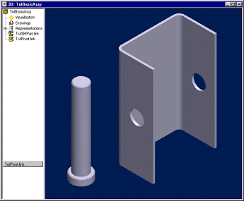
Creating an Assembly from
Existing Parts
You can load the existing parts using, for example, the
context-sensitive menu function Add > Part from Component
Library. All parts added to the assembly are displayed in the
assembly tree.
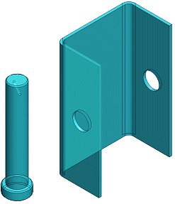
Position the parts using geometric constraints such as
concentric and coincident. Select the parts between which you wish
to add the constraint from the working window. Select, for example,
Constraints > Concentric from the context-sensitive
menu.
Select the surfaces between which you wish to add the
constraint.
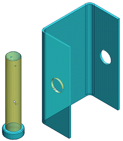
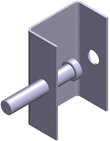
Keep adding constraints until the part is completely
positioned.